Case Histories in Geotechnical Engineering - Paper No. 3.34b
Joseph A. Sopko, Ph.D., P.E. Manager Ground Freezing Services Moretrench American Corporation Port Washington, Wisconsin-USA
Robert Chamberland Project Engineer Moretrench American Corporation Timmins, Ontario-CANADA
ABSTRACT
Artificial Ground Freezing was used to provide temporary earth support and groundwater control for a complex system of three frozen earth cofferdams for the Milwaukee Metropolitan Sewer District’s Harbor Siphons Project in Milwaukee, Wisconsin. Site geometry and frozen earth structural design precluded construction of one large excavation, requiring the component system of the tangential cofferdams. High groundwater velocity prevented the formation of the frozen earth walls during various stages of the project. Remedial methods including external dewatering, permeation grouting, jet grouting, timber shoring and sheet piling were attempted to complete the project. Ultimately a more aggressive ground freezing program was implemented and the project was successfully excavated. The design of the ground freezing system is presented, as well as the difficulties encountered with the high ground water velocity and its impact on freezing. The failed remedial approaches are discussed in detail, including lessons learned. A description of the aggressive ground freezing approach is included as it was the final solution to a complex problem of site geometry and unexpected groundwater conditions.
INTRODUCTION
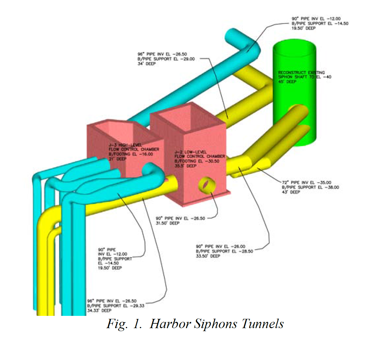
Excavation and installation of connecting sewer lines from the Harbor Siphons Tunnels to the Jones Island Wastewater Treatment plant required excavation through 45 feet of unconsolidated water bearing soils as shown in Figure 1.
Ground freezing was selected as the most technically appropriate method to provide temporary earth support and groundwater control for the excavation required to build the subsurface structures and connecting tunnels. Ground freezing was used successfully on the adjacent drop shaft and two other shafts in the vicinity in the 1980’s. The original concept for the frozen earth excavation system proposed prior to the bid was one large open excavation supported entirely by the frozen earth. The geometry of this excavation resembled a “football” and was named accordingly. Through the entire of the project, the frozen earth system was referred to as the “football” and that term is used within the context of this paper, even though the final design was noticeably different.
As the freezing system design was formalized, structural analyses of the frozen earth indicated that the frozen earth did not exhibit sufficient strength to support and excavation of that size. A series of “cells” were incorporated similar to that used on the CT-8 in Milwaukee (Andersland, Sopko, Shuster 1988).
GENERAL DESCRIPTION
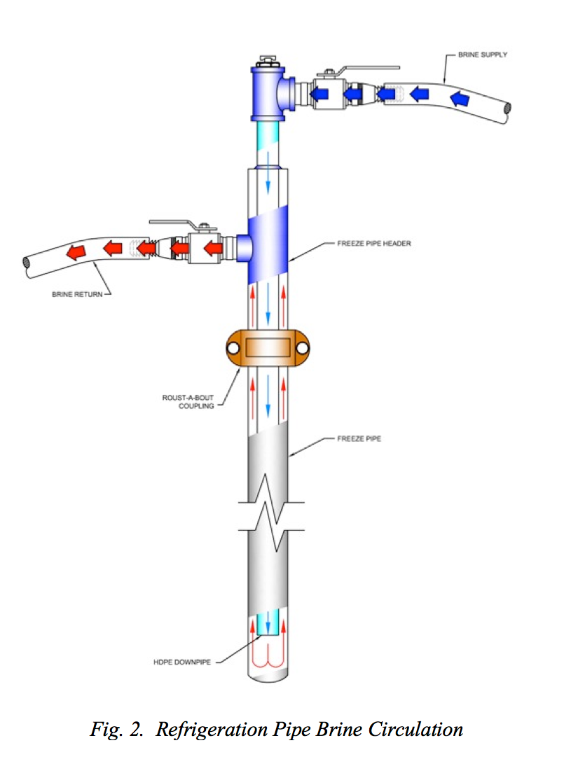
The ground freezing system used on this project was the Poetsch process, patented in the late 1800’s. This process employs a large primary refrigeration plant to chill a secondary coolant that is continuously circulated through a distribution manifold at the ground surface and refrigeration pipes which are embedded in the ground. The entire system is closed; no materials are injected into the ground; the entire process is non-toxic, non-flammable, and non-explosive. The refrigeration plant was powered by commercial electricity.
Detailed data from the site was compiled from the contract documents. The data indicated five distinct soil stratas as presented in Table 1, Generalized Soil Strata Classifications.
While the contract documents provided extensive field and laboratory testing results on the unfrozen soil, the freezing contractor conducted additional boring and frozen soil compressions tests on the organic clay in Stratum II. This was known to be the weakest frozen soil based on previous ground freezing experience in the Milwaukee area.
| Stratum | Description | Depth (ft) | |
|---|---|---|---|
| 1 | Fill | Poorly graded gravel, gravel-‐sand, silty gravel | 0—20 |
| 2 | Estuarine | Organic clay | 20—62.5 |
| 3 | Alluvium | Poorly graded sand, gravelly sand, silty sand | 62.5—85 |
| 4 | Lacustrine | Inorganic clay, silty clay | 85—165.5 |
| 5 | Bedrock | Dolomite | |
| Table 1. Generalized Soil Strata Classification | |||
THERMAL DESIGN
A detailed thermal analysis was not conducted on the project as information was gained on the thermal behavior of the adjacent drop shaft during freezing. Initial formation of the frozen wall would be governed by the behavior of the very soft Strata II organic clay. Subsequent thickening to obtain adequate structural capacity was governed by this stratum. The final design of the ground freezing system required approximately 135 freeze pipes, 3.5 inches in outside diameter ranging in length from 150 feet for each of three individual cells and 50 feet for the interior “buttress” sections between adjacent cells. The pipes were installed vertically at approximately 3.0 feet on center around the perimeter of the plan as illustrated in Figure 3.
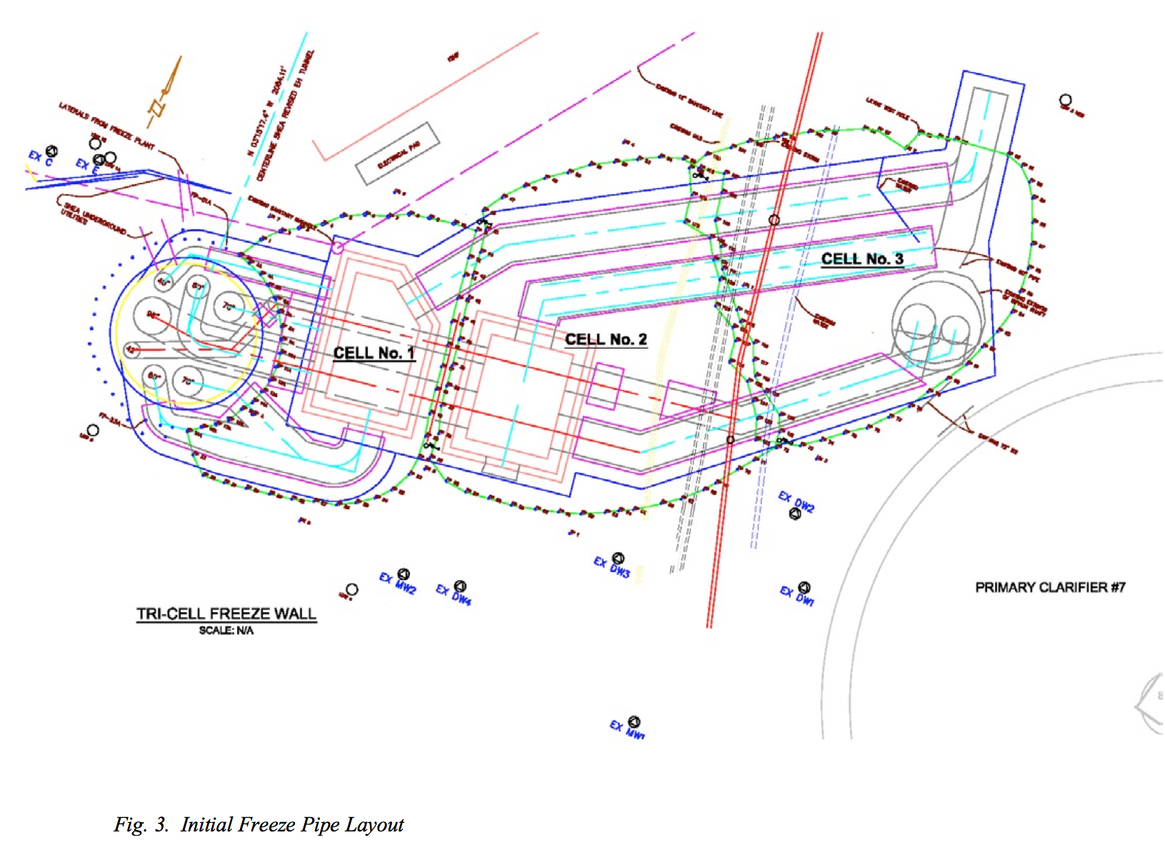
The freeze pipes extended into the underlying bedrock to sufficiently ensure stability of the adjacent excavation. The individual freeze pipes were installed by both resonant sonic ant rotary drilling techniques. The exact “as-built” location of each installed pipe was determined throughout its depth by an orientable inclinometer survey upon completion of pipe installations.
Refrigeration was completed using two electrically driven 350-hp freeze plants that are custom built for the sole purpose of ground freezing. The plants chilled and circulated calcium chloride brine of approximately 1.28 specific gravity through a closed pressure tested manifold system. It was designed to ensure balanced circulation of the coolant throughout all of the refrigeration pipes.
To ensure adequate refrigeration capacity and sufficient flow, each of the three cells was to be turned on sequentially. It requires twice as much refrigeration capacity to form a frozen earth wall than to maintain it. For this reason, the original plan was to start with Cell 1, turn on Cell 2 after the formation of Cell 1, then turn on Cell 3 after the formation of Cell 2. The freezing system was designed to maintain all three cells once they were formed.
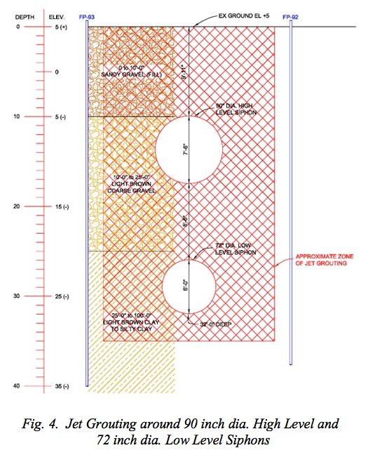
A significant consideration of this project was the need to penetrate the frozen earth cofferdam in Cell 3 by both the 90- inch High Level and 72-inch Low Level Siphons. The technical concern was not so much related to the encroachment of the frozen wall and damage to the siphons as it was the ability to form a frozen seal around the pipes. This is due to the heat introduced into the system by the water flowing within the siphon pipes. A composite wall using jet grouting and ground freezing was used to establish the groundwater control in the Stratum I soil in the vicinity of the pipes as illustrated in Figure 4.
STRUCTURAL DESIGN
Frozen earth behaves plastically, exhibiting time and temperature dependent rheology. Given the geometry of the planned frozen earth structure, the heterogeneity of the ground, unfrozen soil-structure interaction and the inclusion of the non-soil “FREEZEBEAM” reinforcing elements, the problems were best addressed on similar projects as noted in the referenced literature.
Analyses were completed in three phases after separating the entire combined frozen earth structure into several smaller structures (free bodies) that were modeled individually. The following were believed to be the most important factors to evaluate the feasibility of the concept, structural geometry, and approximate state of stress, which may be developed within the frozen earth structure:
- The approximate minimum frozen wall thickness and related state of stress within the relatively circular shaped Cell 3;
- The approximate minimum frozen wall thickness and related state of stress in the buttressed circular arches along the sides of Cells 1 and 2;
- The approximate minimum frozen wall thickness and related stated of stress in the transverse buttress cross wall between the circular arch abutments; and
- The approximate magnitude of stress concentration and means for dealing with it around the openings which were mined through the buttress cross-walls between adjoin, but otherwise independent, frozen earth cofferdams.
HYDRAULIC DESIGN
Bottom stability was considered in the very early stages of the “football” design. To minimize any instability at the base of the excavation, all perimeter freeze pipes were drilled at least ten feet into the underlying bedrock. It was not necessary to drill and install the buttress sections into the bedrock as they do not provide a groundwater barrier. Vertical seepage into the bottom of the excavation from the rock was effectively prevented by the lower permeability soils beneath the excavation and cofferdam.
Lateral groundwater flow was ultimately a severe complication with this project. Lateral groundwater flow introduces energy into the freezing system at a rate greater than the system can remove it. Under these circumstances, the frozen wall was delayed in formation and in fact not even frozen in some areas.
In general, for the frozen earth structure to form properly within the planned schedule there can be no lateral groundwater flow in excess of about three feet per day. The contract documents had indicated that there was no significant groundwater flow when ground freezing was specified as the method to be used for shaft excavation support.
DESIGN SUMMARY
Based on the results of the analysis, the frozen earth structure was assumed to be stable and safe with:
- A somewhat cylindrical frozen earth wall, 6.0 feet in thickness around the Cell 3 perimeter;
- Circular arched walls 6.0 feet in thickness or more along the Cell 1 and Cell 2 exteriors; and
- Transverse, straight buttress wall 8.0 feet or more in thickness between opposing arch abutments incorporating driven steel reinforcing piles to withstand tensile stresses in the mined openings between cells.
HISTORY OF CONSTRUCTION AND COMPLICATIONS
The freezing of the three cells of the “football” was initiated according to plan. The excavation, complications and attempted remedial actions present a case history that exams not only what it took to overcome was what was learned to be excessive groundwater velocity, but what did not work. Many lessons were learned from “what did not work” and can be applied to future frozen earth retaining systems.
Cell 1: The excavation of Cell 1 began on June 1, 2008 and initially proceeded without incident concurrently the partial excavation of Cell 2. On August 1, 2008 Cell 1 excavation was nearly complete when a relatively small water inflow was observed in the northwest corner of the excavation at a depth of approximately 25 feet. In hind sight, this was the first indication of a problem with potential excessive lateral groundwater seepage velocity. However, at the time, it was considered a localized condition. The initial flow was approximately 10 gallons per minute (gpm), but was reduced to 5 gpm immediately after a small pump was installed in a monitoring wall adjacent to the frozen earth wall with an interval screened in the alluvial material.
Following the installation of the pump, liquid nitrogen was used in the affected area of the freeze system to try to reduce and then stop the groundwater flow into the excavation. This attempt was unsuccessful, but the nitrogen flow was continued to significantly lower the temperature of the surrounding soil in order to prevent a breach in the frozen wall. The liquid nitrogen was discontinued when the Cell 1 excavation was completed on October 1, 2008. Full excavation began immediately.
Cell 2: When excavation began in Cell 2 a massive frozen wall nearly 30 feet thick was encountered which was particularly prevalent on the north side. Again, the initial excavation proceeded without incident. The excavation on the south side then began to encounter complications. To address these complications, on November 3, 2008, ten solider piles were drilled into the interior of Cell 2 that were incorporated with a lagging system to assist in the support of the south wall.
However, as the continuing excavation approached 35 feet deep, groundwater inflows were observed coming in to the excavation directly through a coarse-grained seam that measured approximately five feet in width. Excavation ceased at that point and twenty grout pipes were installed on the south side of Cell 2. A pressure grouting procedure was initiated using a combination of cement bentonite grout. The grout was initially mixed at a 4:1 water to cement ratio, and as the pumping continued it was increased to 1:1 in an attempt to close off the apparent excessive groundwater seepage to allow the freeze system to take hold and create the needed frozen wall in the area. The grouting operations continued from December 2008 to mid-January 2009.
During this process the ground temperatures were monitored and it was concluded that the ground was not freezing. In an attempt to seal the alluvial seam, a jet grout wall was installed on the south side of Cell 2, the same area that the pressure grouting was used. The jet grouting operation began on December 18, 2008 and continued to January 9, 2009. As a part of the remedial operation, monitoring wells were installed on January 7, 2009. Temperature profiling of the freeze pipes continued from January 13 to 19. A description of temperature profiling is found in the literature (Sopko, Braun 2000).
Unfortunately, despite all of these efforts, groundwater was once again observed flowing into the excavation on January 22, 2009 just after excavation was resumed. In attempt to reduce groundwater flows into the excavation four dewatering wells were installed on the south side of the “football”. All of these extra measures proved unsuccessful as the water flow continued and created a hydrostatic head beyond the capacity of the grout and lagging support system. On February 4, 2009, the upper 20 feet of the south side of Cell 2, including the soldier pile and lagging system collapsed.
With this collapse, the groundwater conditions were re- evaluated and it was concluded that the groundwater velocity in that alluvial seam was greater than the reported 3 feet per day, clearly exceeding the capacity of the ground freezing system. Additional freeze pipe profiling was completed along with additional soil borings and grain size analyses. Results of this investigation concluded that the permeability of the alluvial soils was significantly greater than what was originally anticipated. This high permeability, coupled with measured groundwater gradients across the site.
To ensure construction continued, a sheet pile “box” was installed within the interior of Cell 2. While the ground behind the sheet pile wall froze around the majority of the cell, there was still groundwater seepage from the south side, the sheet piling system permitted the majority of the excavation of Cell 2.
Cell 3: Cell 3 was considered the most difficult and potentially risky excavation of the three cells. It was not only the deepest, but after having to adjust the freeze pipe geometry to compensate for the adjacent clarifiers, the geometry had less curvature than originally planned. At this point in the project, the ground temperatures indicated several warm, unfrozen zones. Additionally groundwater inflows from Cell 2 were still being observed.
The unfrozen zones across the entire side were limited to the relatively thin lens of alluvial material where it was know that the groundwater velocity exceeded three feet per day. Even if the majority of this seam could be frozen, a small breach with groundwater intrusion would increase in size very rapidly and melt the material around the entire excavation.
Ground freezing had been originally selected for the support of excavation almost through a process of elimination. While freezing is typically more expensive than conventional sheeting, solider piles and lagging and sometimes slurry diaphragm walls, it was the only method technically appropriate. Freezing however has its limitations when there are excessive groundwater velocities.
Evaluation of the conditions of the football continued with focus on alternate methods to either augment or even replace the freezing. The conclusion among the consultants, the contractor and the owner was that freezing was the only method that could work. Moving groundwater in the alluvial material was not something new to ground freezing in Milwaukee. During the 1980’s deep tunnel project, several projects experienced the same difficulty. In each of those cases, remedial action that included permeation grouting and increased refrigeration permitted the freezing system to overcome the high groundwater velocity.
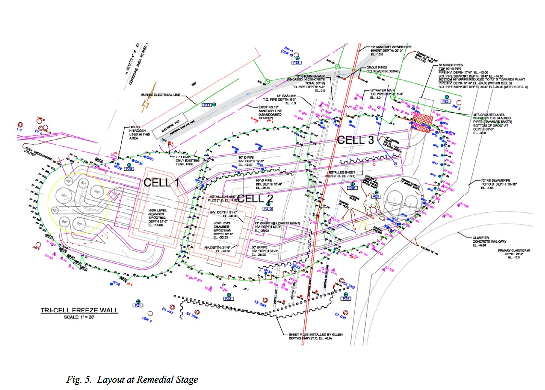
REMEDIATION AND COMPLETION
To expedite completion of the project, the original freezing contractor was relieved of his contractual obligations and another company mobilized. The replacement freezing contractor evaluated the situation and reviewed what had worked in the 1980’s. A new plan of attack was formulated and summarized as follows:
- Backfill all cells to grade;
- Conduct temperature profiling in every individual freeze pipe to locate warm zones;
- Inject cement grout into the warm zones and add additional freeze pipes;
- Increase refrigeration capacity by adding another mobile freeze plant;
- Increase coolant flow by adding additional pumps; and
- Allow sufficient time for the frozen earth wall to form.
After approximately six weeks of freezing, ground temperature data indicated that the alluvial seam was frozen across the entire project. Excavation proceeded without any indication of groundwater intrusion. While there was no groundwater, excavation was somewhat difficult and did not proceed as rapidly as planned.
While there were many problems with groundwater flow in the alluvial material due to the high groundwater velocity, the other material continued to freeze as originally planned. With over one year of freezing, the thickness of the frozen wall in these other layers continued to increase with time. While the additional frozen material outside the structure added significant structural capacity to overcome the lack of curvature in Cell three, the excavation of the inside was tedious.
Excavation of the inside was completed with hoe rams and pneumatic spades and without any additional consequences. The project was completed in the required seasonal time frame to allow the transition of sewers entering the Jones Island Wastewater Treatment Plant.
LESSONS LEARNED
Without a doubt, the most important lesson learned on this project was that ground freezing is a very valuable technique as long as the groundwater velocity is not excessive. All of the remedial activities in Cell 2 were attempted without completely backfilling the excavation and control the ground water. When breaches in frozen walls are encountered, time proven approaches should be implemented. These steps, the same used in the 1980’s are summarized:
- Locate the warm zone through temperature profiling;
- Backfill or flood the structure;
- Inject permeation grout into the warm zones;
- Add additional refrigeration pipes to the affected areas;
- Ensure that there is adequate refrigeration capacity and sufficient coolant flow; and
- Most importantly, allow enough time for the frozen wall to form.
These lessons learned provide a simple, straight-forward approach to resolving problems in forming frozen earth walls where there is excessive groundwater velocity. These lessons, in addition to the design methods, the reinforcement with the FREEZEBEAM and field quality control and assurance made the Jones Island “Football” a significant milestone in ground freezing technology.
REFERENCES
SOPKO, J.A. and BRAUN, B. [2000] “Investigative and Remedial Methods for Breach in a Frozen Shaft”. Ground Freezing 2000, Thimus (ed.) © 2000 Balkema, Rotterdam, ISBN 90 5809 170 8 pp. 339-344.
SOPKO, J.A. and ANDERSLAND, O.B. [1991] “Frozen Earth Cofferdam Design” Procedures of the Sixth International Symposium on Ground Freezing. Beijing, China
SOPKO, J.A. [1990] “New Design Method for Frozen Earth Structures With Reinforcement.” Unpublished, Ph.D. Thesis, Dept. of Civil Engineering, Michigan State University, East Lansing, MI.
