GeoMontréal 2013
ABSTRACT
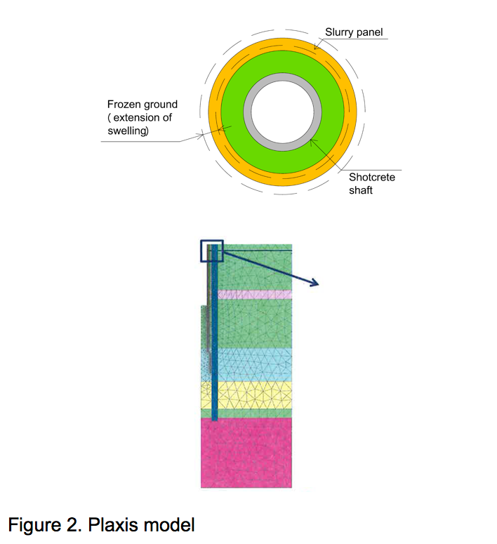
The 15 km long Southeast Collector (SeC) Gravity Trunk Sewer will augment the existing York Durham Sewage System (YDSS) accommodating the anticipated population growth in the York Region of Ontario, Canada. The project includes the construction of three shafts for diversion facilities, 13 permanent access and maintenance shafts and two drop structures. Four Earth Pressure Balance Machines (EPBM) will mine the sewer tunnel. In advance of the Tunnel Boring Machine (TBM) drives to launch, inspect and retrieve the TBMs, 16 shafts and three strutted excavations will be constructed along the sewer alignment. The overburden soils consist of preconsolidated glacial till and glaciofluvial gravel, sand, silt and clay deposits overlaying Ordovician-age bedrock. The shafts are excavated in overburden soil material to a maximum depth of 51 m below the surface. The bedrock shale formation is utilized by several deeper shafts for groundwater cut-off. The diameters of the shoring system range from 4.6 m to 15.6 m. Active dewatering is generally not acceptable for the project to avoid influencing the groundwater table. For the temporary support of the shaft excavations, secant pile walls, diaphragm walls, shotcrete lining, ground freezing and combinations are used. Unexpected difficulties during one shaft excavation required changing the approach completely and converting to ground freezing. The previously installed shotcrete lining was not designed for the forces associated with the freezing process. The behavior of the frozen ground was evaluated using both thermal and structural modeling programs. In-situ stress and deformation was measured to confirm the results of the modeling program and to gain insight to the interaction of the frozen earth and the temporary shaft lining for use on subsequent shafts on the project.RÉSUMÉ
Le système d’égout collecteur à gravité du sud-est (SEC) d’une longueur de 15 km va permettre d’améliorer le système d’égouts de York Durham (YDSS )pour répondre aux besoins croissants de la population prévue dans la région de York située en Ontario au Canada. Le projet inclut la construction de 3 puits afin de faciliter le détournement 13 puits pour un accès permanent et pour l’entretien en plus de 2 structures pour chutes. Le tunnel d’égouts est creusé par 4 machines à pression équilibrée (EPBM). Avant d’introduire la machine TBM pour la construction des tunnels, il faut construire 16 puits pour permettre l’inspection et l’entretien de celle-ci. La partie sous-terraine rocheuse de l’Ordovicien est recouverte de plusieurs couches de gravier, de sable et de glaise. Les puits sont creusés jusqu’à un maximum de 51m afin d’atteindre la profondeur requise. La formation de la roche de schiste est utilisée pour les puits plus profonds pour isoler l’eau souterraine. Les diamètres de la gamme du système d’étayage sont de 4,6m à 15,6m. Une déshydratation active n’est pas acceptable pour le projet afin d’éviter tout impact sur la nappe phréatique. Pour le support temporaire de l’excavation des puits, nous avons utilisé plusieurs procédés comme : les murs de pieux sécants, des parois moulées, des doublures de béton, et le gélisol (gel du sol). Des difficultés imprévues durant l’excavation d’un des puits a nécessité le changement au complet de l’approche en utilisant seulement la méthode de gélisol (le gel du sol). La couche de béton précédemment utilisée comme doublure n’est pas conçue pour les forces associées à la procédure de congélation. Le comportement du sol gelé a été évalué à l’aide de deux programmes de modélisation thermique et structurale. La déformation et les contraintes en situ ont été mesurées pour confirmer les résultats du programme de modélisation et pour mieux comprendre l’interaction de la terre gelée et de la doublure du puits temporaire.1 BACKGROUND
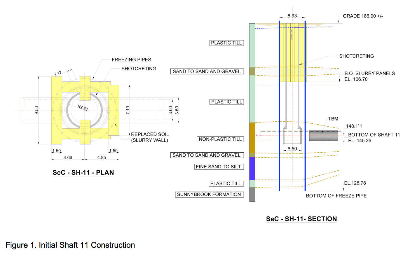
The general contractor selected ground freezing as a technically appropriate alternative to provide temporary earth and groundwater support during excavation. Ground freezing was selected for several factors. Due to unexpected very hard soils and presence of numerous boulders, construction of the slurry panels were stopped and limited to short panels with a 20m depth to cut off the upper aquifer around the shaft. It was determined that rotary drilling of the freeze pipes could accelerate the schedule. Additionally, ground freezing facilitated deeper penetration of the impervious wall contributing to basal stability in soils where underlying bedrock was not present. The preliminary discussions between the general contractor and specialized ground freezing subcontractor, as well as a review of geotechnical information indicated that the overburden soils would exhibit sufficient frozen strength to support excavation of the entire shaft until it is lined and the freezing operation terminated.
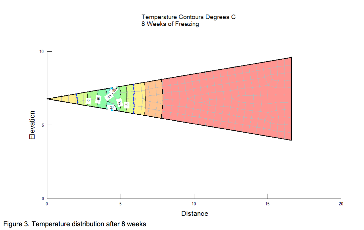
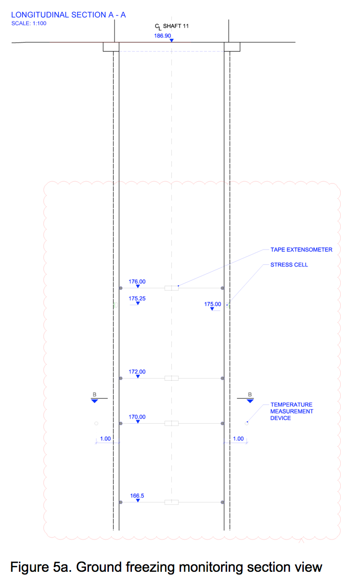
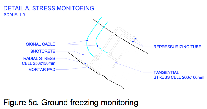
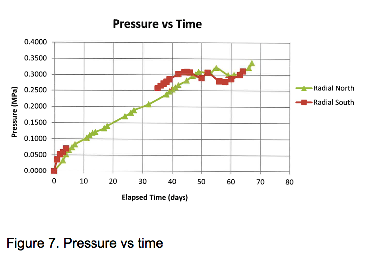
To avoid any delay in construction schedule, without waiting for the formation of the freezing, it was decided to proceed with excavation and shotcrete from the surface to a depth of 28 meters which was located entirely in plastic till with the exception of a 3.20-meter layer of sand to sand and gravel (stratum 2) which had been already cut off by executed slurry panels. Just before starting of the excavation of the shaft, required freezing pipes were installed and connected to the plant and then the freezing formation process was commenced. Concurrently with the formation of the freezing, excavation and shotcreting was in process in the upper 27meters. The shotcrete had been designed to be resistant to ground and water pressure after de-activation of the freezing. An extra 50mm of the shotcrete was applied and considered an insulation layer. In order to monitor the frost pressure on the shaft’s shotcrete lining during formation, tape extensometers along with radial and tangential stress cells were installed to indicate shotcrete lining radial deformation and freezing stresses in both radial and tangential directions. Excavation and shotcreting between 28m to 42m depth was continued after ensuring completion of the freezing formation as indicated by the data obtained from the temperature monitoring pipes and the internal piezometer in the center of the shaft. In the later stage, while the ice columns were growing, installed extensometers and stress cells indicated deformation and developed stresses due to the frost pressure on the shotcrete lining in upper elevation. Some surface cracks were observed at 17m. In order to control the situated stresses and crack, the freezing temperature was raised from approximately -35oC to -10oC which was helpful to control and reduce the frost pressure on the shotcrete lining. The cracked surface was repaired before de-activation of the freezing to ensure the originally designed structural capacity.2 GROUND FREEZING DESIGN
The ground freezing system that was used for this project was the Poetsch process, developed in the late 1800’s. It employs a large primary refrigeration plant to chill a secondary coolant that is continuously circulated through a distribution manifold at the ground surface and refrigeration pipes which are embedded in the ground. The Poetsch process has been employed successfully on ground freezing projects for over one hundred years, including over 25 shafts in similar soils in the Milwaukee and Detroit areas. It is a proven and reliable means of stabilizing the earth and controlling ground water. Detailed geotechnical data from the site were compiled and provided to the contractor. Tables 1 and 2 summarize the soil properties used in the design of the ground freezing system.| Stratum | Soil Composition | DepthUpper(m) | DepthUpper(m) |
|---|---|---|---|
| I | Clayey silt till to clay till-plastic | 0.0 | 15.2 |
| II | Sand to sand and gravel; non-plastic | 15.2 | 18.4 |
| III | Clayey silt till to silty clay till; plastic | 18.4 | 34.1 |
| IV | Fine sand and silt till; non-plastic | 34.1 | 45.1 |
| V | Sand to sand and gravel; non-plastic | 45.1 | 46.6 |
| VI | Fine sand to silt; non-plastic | 46.6 | 54.2 |
| VII | Clayey silt till to silty clay; plastic | 54.2 | 56.7 |
| Table 1. Subsurface soils | |||
| Stratum | I | II | III | IV | V | VI | VII |
|---|---|---|---|---|---|---|---|
| Total Unit Weight (k/m3) | 22 | 22 | 22 | 22 | 22 | 22 | 22 |
| Effective Unit Weight (k/m3) | 12 | 12 | 12 | 12 | 12 | 12 | 12 |
| Moisture Content (%) | 10 | 10 | 90 | 90 | 11 | 10 (est) | 10 (est) |
| Effective Friction Angle (deg) | 35 | 37 | 35 | 37 | 37 | 37 | 35 |
| At-rest Earth Pressure Coefficient | 1.2 | 0.8 | 1.2 | 1.0 | 0.8 | 0.8 | 1.2 |
| Active Earth Pressure Coefficient | 0.27 | 0.25 | 0.27 | 0.25 | 0.25 | 0.25 | 0.27 |
| Table 2. Soil Parameters and Design Values | |||||||
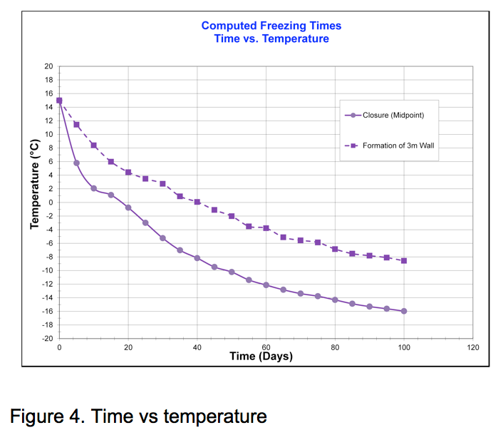
The first step in most freeze designs is the structural analysis. In this phase the thickness of the frozen earth wall surround the excavation is determined. The thickness of the frozen earth wall is governed by several components, the lateral earth pressure acting on the frozen mass, the compressive strength of the frozen soil, the temperature of the frozen soil, and the length of time the excavation will remain open before lining.
Frozen earth behaves plastically, exhibiting time and temperature dependent rheology. The following were believed to be the most important factors to evaluate to determine the structural geometry and approximate state of stress that may be developed within the frozen earth structure:- The approximate frozen wall thickness and related state of stress in the cylindrically shaped structure; and
- The allowable excavation time before the final lining is installed.
