New York City Water Tunnel No. 3
Manhattan Portion, Phase II
Shaft Excavation and Construction
New York, NY
Ground Freezing
Scheduled to be completed in 2020, City Water Tunnel No. 3 will eventually span more than 60 miles, and represents the largest capital construction project in New York City’s history to date. The new tunnel system is designed to improve distribution capability as well as to meet the ever growing demand on the existing water supply, and will allow the New York City Department of Environmental Protection (NYCDEP) to inspect and repair the active Tunnels 1 and 2 for the first time since they were put into service in 1917 and 1936 respectively.
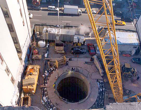
The tunnel alignment lays hundreds of feet below ground in the ancient metamorphic, granitic rocks underlying the city, with many of its deep, vertical access shafts rising through glacial deposits and water-bearing sands above bedrock. The shafts are situated in the dense urban environment which they serve; most must be located within tight spaces available in congested city blocks. In such circumstances, the NYCDEP places a high priority on protecting adjacent structures from damage during shaft excavation and construction and specified ground freezing because of its reliability and track record in New York City. Working under the joint venture of Schiavone/Shea/Frontier- Kemper, Moretrench used artificial ground freezing to provide ground support and groundwater control protection at five shaft locations in midtown Manhattan.
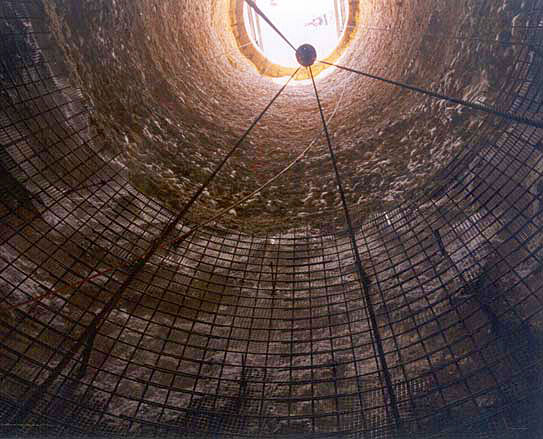
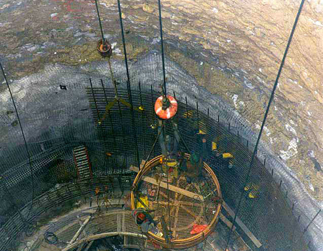
The upper portion of the shafts within the overburden were excavated to a diameter of 35 feet and a completed diameter of 26 feet and were to be advanced through the overburden and 50 feet into rock. Depth to groundwater at the shaft locations ranged from 15 to 45 feet. Variation in overburden thickness required that the freeze pipes and temperature monitoring pipes be installed to depths ranging between 75 and 130 feet from ground surface, extending 15 to 30 feet into underlying bedrock. To accomplish the ground freezing, Moretrench utilized mud rotary drilling techniques to advance the 4-inch diameter steel pipes to design depth. Each shaft location was equipped with a refrigeration plant, with capacities ranging from 120 to 150 tons. All five shafts were frozen concurrently.The contractor was able to raise bore the five shafts from the water tunnel 500+ feet below ground surface to approximately 10 feet below top of rock at an approximate depth of 110 feet below ground surface, excavate the shafts to top of bedrock, and drill and blast the bedrock plug all before slip-forming the final concrete lining. During the 6- to 8-month shaft excavation period, and blasting and slip forming, the frozen wall was insulated with polyurethane foam and reinforced with wire mesh.
Excessive groundwater movement presented an unanticipated problem at two shafts. Here, groundwater was measured approximately 10 feet below sea level, due to a major withdrawal of several thousand gpm of groundwater a few blocks away. The groundwater velocities encountered at the shafts prevented proper freeze formation. Ground temperatures measured within the freeze pipes themselves indicated the presence of an upstream “entrance” and a downstream “exit” window due to the movement of groundwater through the shaft. Piezometers throughout the site confirmed that the groundwater within the shaft was still in direct communication with the outside groundwater regime. Moretrench performed a program of permeation grouting to successfully reduce the permeability of the pervious zones within the aquifer and closure of the shaft was achieved. The success of freezing at these locations is due to early diagnosis of the moving groundwater and timely implementation of grouting. An extensive instrumentation and monitoring program was instrumental in performing this.


